Keep this information on hand
  • Car Defender User Guide

    • EN50131-2-8-2016
    • EN50131-5-3:2017
    • EU 2015/853 | UK RoHS regulation 2012
    • 2014/53/EU | Radio Equipment Regulations 2017 (RED)
    • Specifications

      Specification Value
      Dimensions and weight
      (W x H x D)
      Device – 30 x 95 x 10mm, 30g
      Holder – 122 x 163 x 12mm, 35g
      Casing / Colour Device – 2mm polycarbonate-ABS, anthracite
      Holder – Silicone strap, yellow | UV Additive RIASORB UV-329 holder, black
      LED colours Red, blue and green
      Detection methods Shock only | tilt only | tilt or shock
      Tilt alarm threshold ~4°
      Shock sensitivity Low, medium and high
      Battery 2 x lithium CR2450R , 3V,500mAh with a 50mA pulse
      Temperature Storage: -20°C to 50°C
      Operating: -10°C to 40°C
      Emissions EN55032 Class B
      Immunity compliance EN50130-4
      Environmental class II

    • Inserting and Removing Device

      To insert the device into the holder, it just needs to be firmly pushed in.
      To remove the device from the holder, the device requires pushing out via the hole in the back of the holder.
    • Attaching to Steering Wheel

      1. First, wrap the strap around the wheel.
      2. Then, insert the locking mechanism under the hook.
      3. Push the locking mechanism up around the back of the hook.
      4. To lock in place, push the tab of the locking mechanism down so that the top slides into the hook.

      The holder can be used to attach the device to other objects, however, it is designed for use with vehicle steering wheels.

    • LED Visibility

      Please note: The enabling and disabling the LEDs only relates to ‘Detection Mode Setting’ and ‘Detection Mode Check’. The B2H function will still operate

      Auto-disable

      The calibration status LEDs will turn off after a period of 10 minutes and the blue alarm LED will turn off after a period of 1 hour from:

      • Device is powered up.
      • The case being closed (which presses the ‘setting activation button’ in).

      Re-activating the LEDs

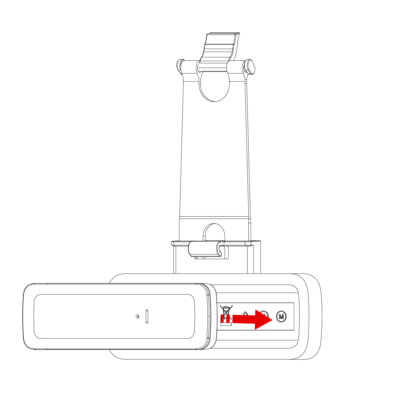
      The calibration and alarm LEDs can be reactivated by any of the following methods.

      • Opening the case (activating the setting activation button on the device).
    • Multi-Functional Button
    • Overview

      Detection mode setting

      A 6 second press puts the device into detection mode setting where the sensitivity can be changed.

      Detection mode check

      A 3 second press is used to check the configuration setting the device is currently set to.

      Back to Home (B2H)

      Short press (less than 1 second). Polls the panel to check whether the device is in range.

    • Detection Mode Setting

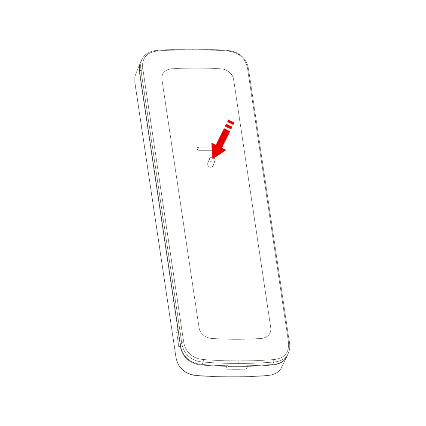
      A 6 second press puts the device into configuration mode where the sensitivity can be changed.

      Description Sensitivity level Blink Red Green Blue
      Tilt only Fixed 4° 1 all LEDs
      Shock only Low 1
      Medium 2
      High 3
      Tilt or shock Low 1
      Medium 2
      High 3
      Tilt Only

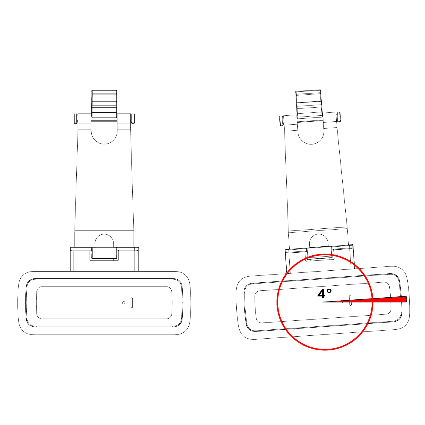
      There is one sensitivity setting for the tilt mode. The angle of tilt required to trigger the detector is ~4°.

      Shock Only

      There are 3 sensitivity settings for the shock mode, low, medium, and high.

      Shock is someone hitting the vehicle or an intruder attempting to break a window or a lock. If set to high, the device is more sensitive to shock activation.

      Tilt or Shock

      In this mode, if the device is triggered via tilt or shock, it will signal an alarm.

      Note
      The 10 minute detection mode setting timer (along with the LEDs) can be restarted by either:

      • Opening the case (activating the setting activation button on the device).

      Tilt Mode Detection

      When movement is detected, it is then analysed by the unit and if the movement threshold angle is exceeded, an alarm will be generated.
      Tilt or movement more than ~4° on the x or y axis from the “home position” will constitute as movement.

      Please note: The degree of angle given to constitute movement is an approximation.

    • Detection Mode Check

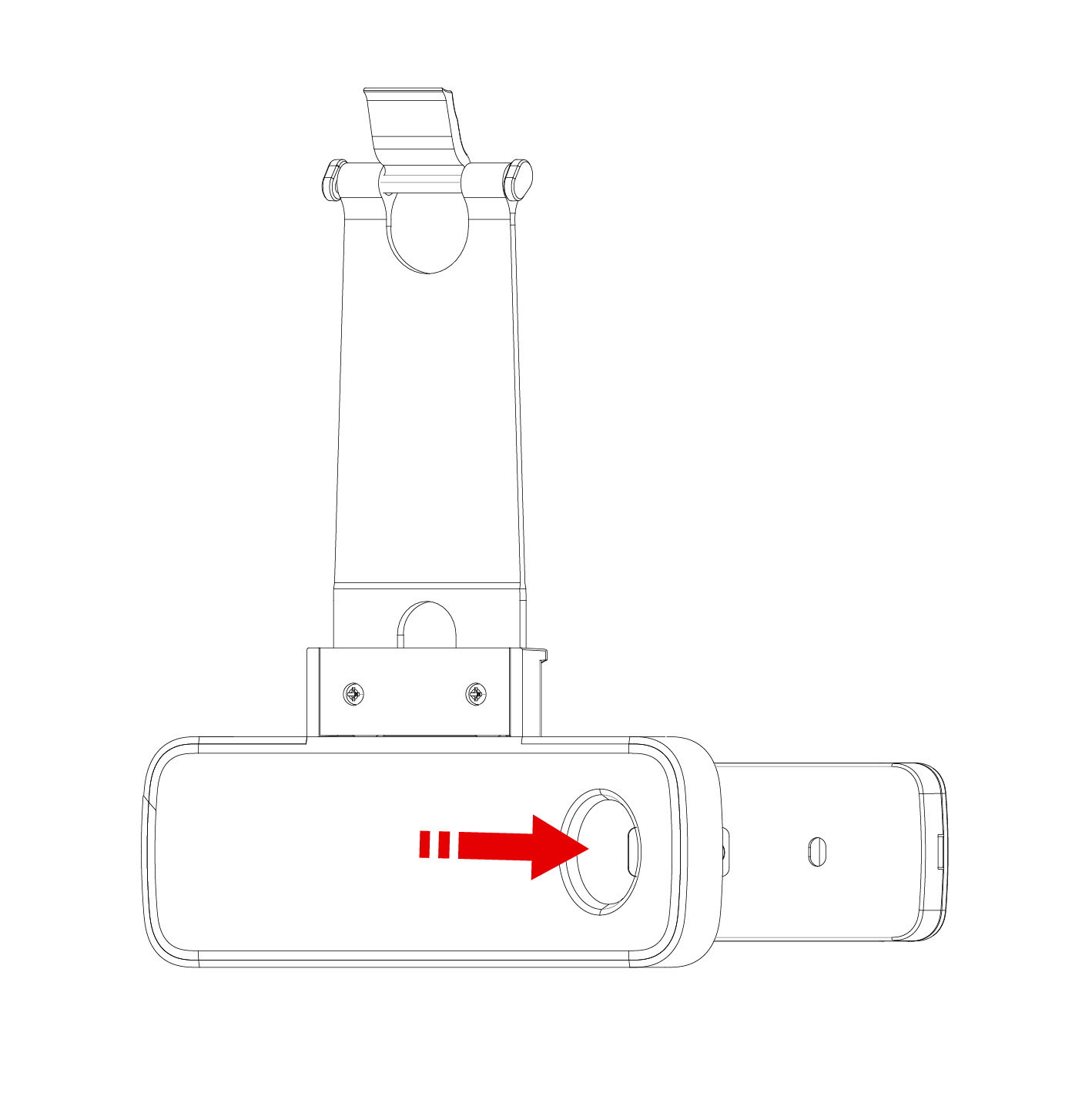
      If the button is pressed and held for 3 seconds, the LEDs will indicate what the detection mode is set to.

      Please note: In order for detection mode to work, the LEDs must be activated.

    • Back to Home (B2H)

      Back to Home (B2H)

      If the button is pressed for 1 second and released, the device polls the panel to check whether the device is in range of the system.
      This is the only function relating to the LEDs that will still function after the 1 hour timer has expired.

      Blue flash then green
      Indicates the device is within range of the system and has good signal strength.
      Blue flash then red
      Indicates the device is within range of the system but has bad signal strength.
      Blue flash only
      The device has polled the system but has not had a response therefore it is out of range.


    • Home Position

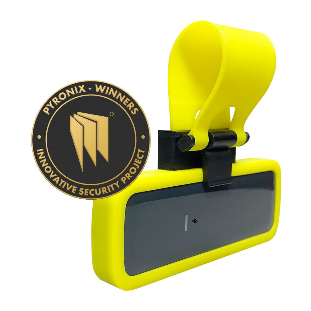
      The “Home Position” is the installation position of the device. Once a “Home Position” has been determined by the device, if the device is triggered, it will signal to the system it has been triggered.

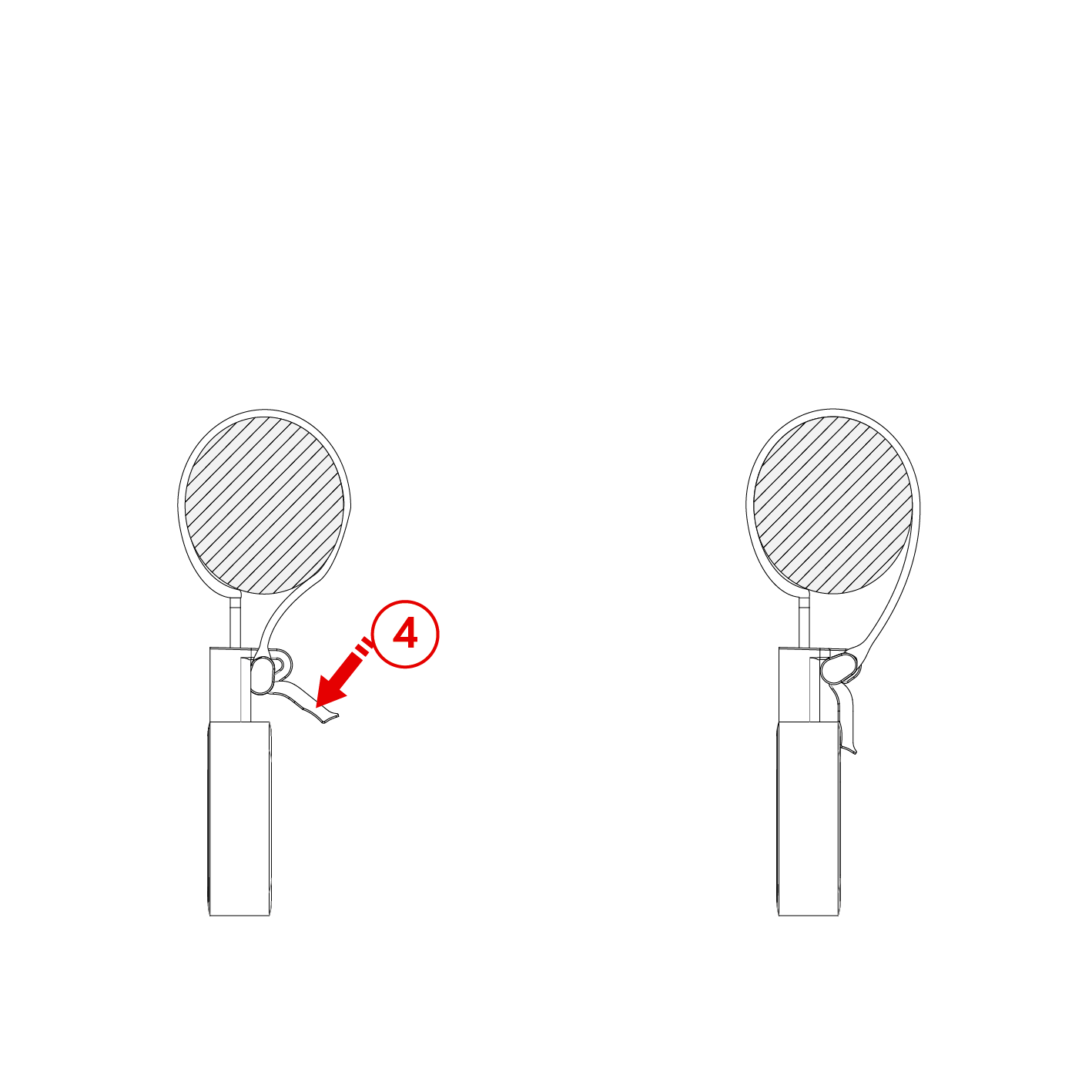
      The device will calibrate its “Home Position” after the following scenarios:

      • After a period of 4 seconds once the case is closed.
      • After a period of 10 seconds following an alarm activation.

      The device can be relocated wherever the user sees fit when the system is disarmed (providing the zone is not programmed as 24 hour or day alarm).

    • Battery Information

      The batteries supplied have been chosen to provide long service life whilst, for safety reasons, having limited output current.
      The battery is protected on purchase by a piece of plastic that must be removed for operation. When disposing of the product, the battery must be removed and disposed of separately in accordance with the local regulations

      Replacing the batteries

      Important: When replacing the batteries in the device, both batteries must be replaced at the same time.
    • Product Warning Information

      For electrical products sold within the European Community. At the end of the electrical products life, it should not be disposed of with household waste. Please recycle where facilities exist. Check with your Local Authority or retailer for recycling advice in your country.

      To prevent possible damage to components, any static charge on your body needs to be eliminated before touching the inside of the unit. This can be accomplished by touching some grounded/earthed metallic conductor such as a radiator/pipework immediately before replacing the batteries.

    • Warranty

      This product is sold subject to our standard warranty conditions and is warranted against defects in workmanship for a period of two years (battery excluded). In the interest of continuing care and design, Pyronix Ltd reserves the right to amend specifications, without giving prior notice. Please see the control panel programming manuals for further information or visit: www.pyronix.com/uk/terms-conditions-sales/