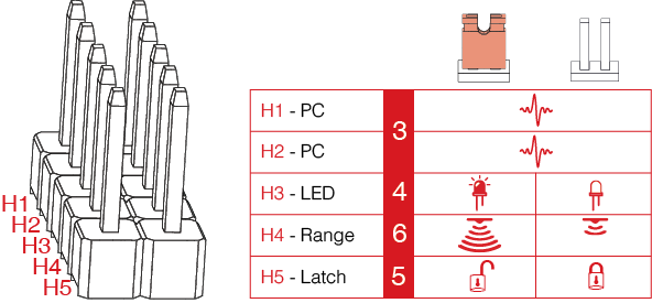
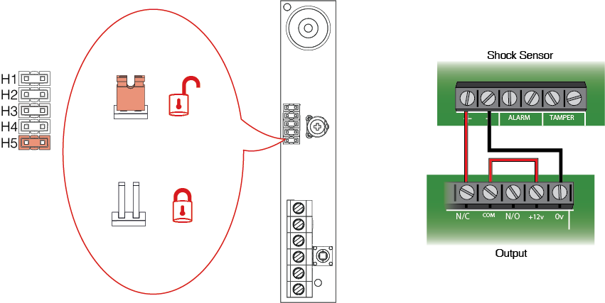
H1 and H2 are used to select the pulse count.
H3 enables or disables device LEDs, remove to disable LEDs.
H4 is to select high or low sensitivity range, remove for low range.
H5 is used to select LED latch on activation, remove for LED latching.
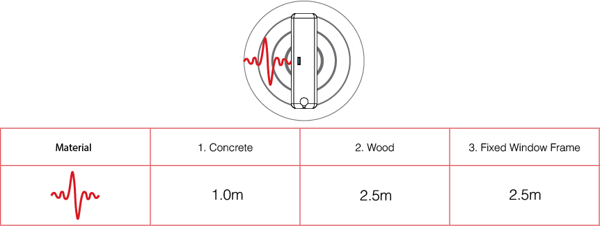
The values shown in the table indicate typical values on various materials. The materials shown (reading from left to right) are concrete, wood and a fixed window frame.
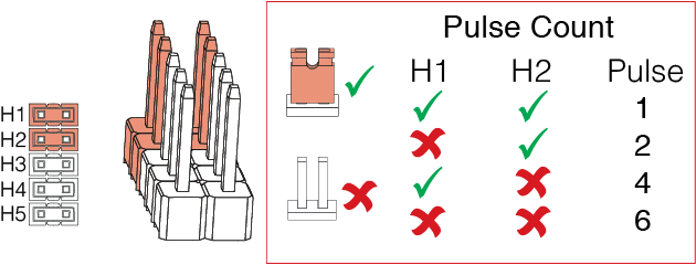
Use H1 and H2 to set the pulse count needed to trigger the device into alarm. Each time the pulse count setting is changed, the LED will flash the appropriate number of times to indicate which setting is selected. It will verify this by indicating the pulse count setting 3 times, pausing between each verification.
The LED will flash on initial power-up and each time the pulse count setting is changed. Use the H3 jumper to enable or disable LEDs.
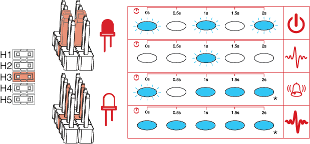
Remove the jumper from the H5 (or put on just one pin so that the jumper is not lost) to activate the latching feature. If this feature is activated and the sensor is triggered, the LED on the sensor will stay on in order to display that it has been activated. To reset, the power must be removed from the device.
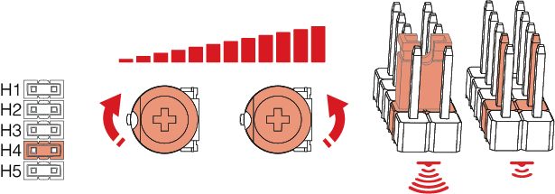
Adjust clockwise to increase sensitivity and anti-clockwise to decrease sensitivity. Use H4 to set high or low range. If the sensor detects ‘gross attack’ (a vibration higher than the calibrated sensitivity), it will override the pulse count and go directly into alarm.
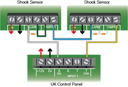
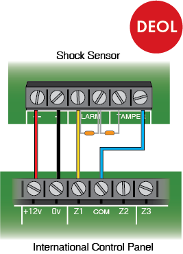
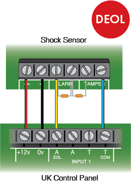
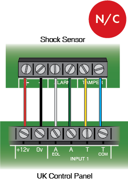
Examples of wiring the device to a control panel.
For electrical products sold within the European community. At the end of the electrical products life, it should not be disposed of with household waste. Please recycle where facilities exist. Check with your Local Authority or retailer for recycling advice in your country. To prevent possible damage to components, any static charge on your body needs to be eliminated before touching inside of the unit.
This product is sold subject to our standard warranty conditions and is warranted against defects in workmanship for a period of five years. In the interest of continuing care and design, Pyronix Ltd reserves the right to amend specifications, without giving prior notice.
 Arming Devices
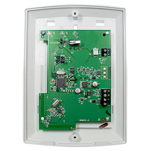
 Communication Devices
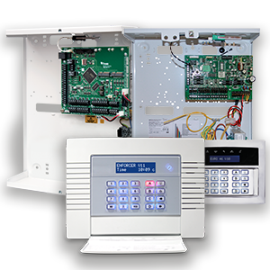 Control Panels
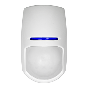 Detectors & Sensors
 Expanders
 Legacy Products
 Smart Home Devices
 Software & Services
 Sounders & Bells
 Wi-Fi Cameras