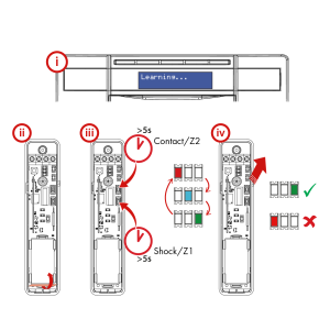
i. Prepare the system for pairing with the device.
– Please refer to control panel instructions.
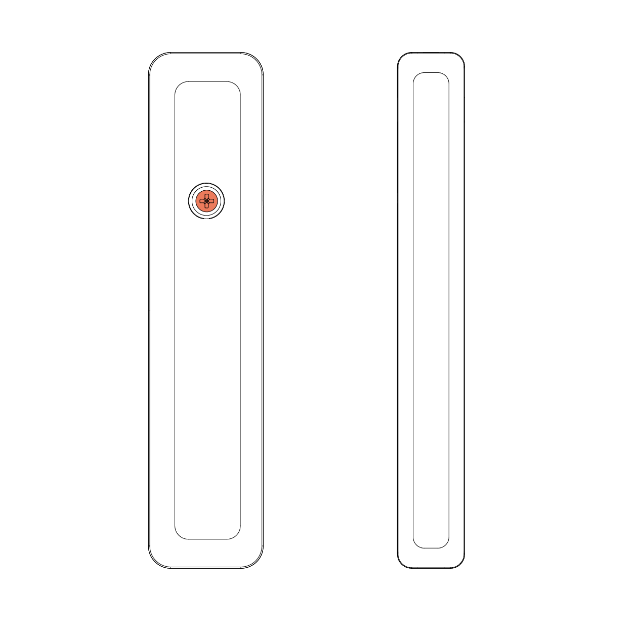
ii. Remove the piece of polyester film that is separating the battery from the battery contacts.
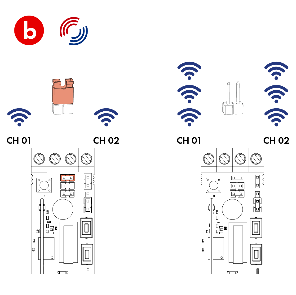
iii. Press and hold the ‘learn button’ on the device for at least 5 seconds and then release.
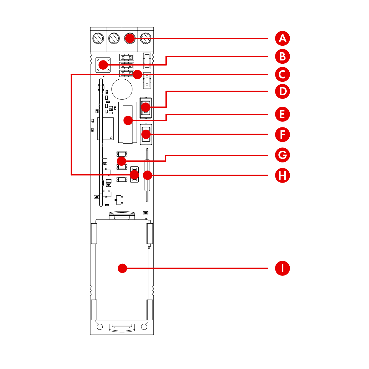
– To learn the shock sensor or zone 1 external input, press the bottom button.
– To learn the magnetic contact or zone 2 external input, press the top button.
– The three LEDs will cycle through on the device whilst the button is held.
iv. On releasing the learn button, the device attempts to pair with the system and will indicate via the LEDs whether it has been successful or failed.
– ![]() The red LED will flash 5 times to indicate the device has successfully paired zone 1 with the system and has adequate signal.
The red LED will flash 5 times to indicate the device has successfully paired zone 1 with the system and has adequate signal.
– ![]() The green LED will flash 5 times to indicate the device has successfully paired zone 2 with the system and has adequate signal.
The green LED will flash 5 times to indicate the device has successfully paired zone 2 with the system and has adequate signal.
– If the device fails to pair with the system, the device will return to the alternating flashing green and red.
![]()
Once learnt to the system, the zone or zones need to be programmed so that the system responds as intended when the device is triggered.
Please note: Refer to the installation or programming guides provided with the control panel for advice.
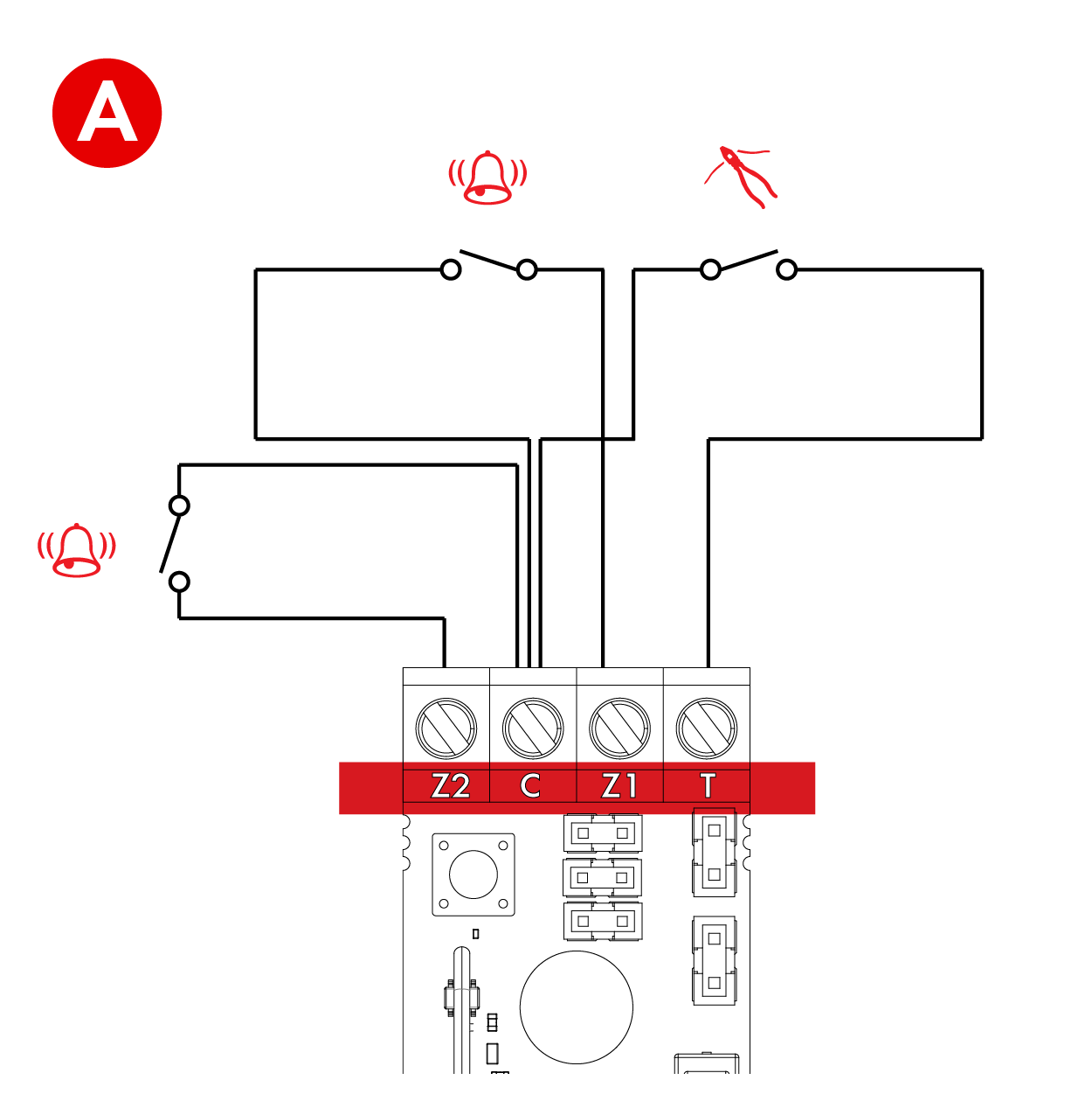
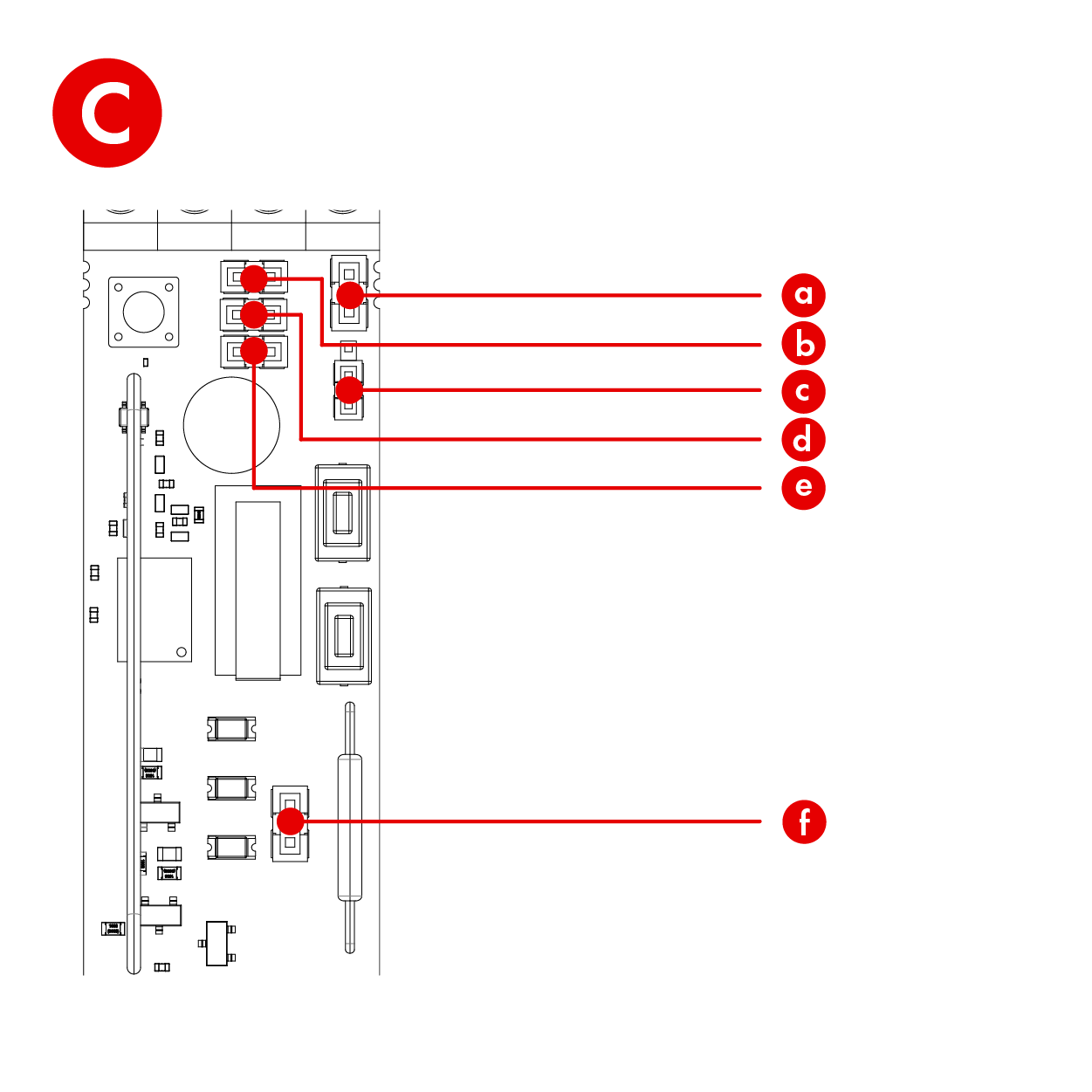
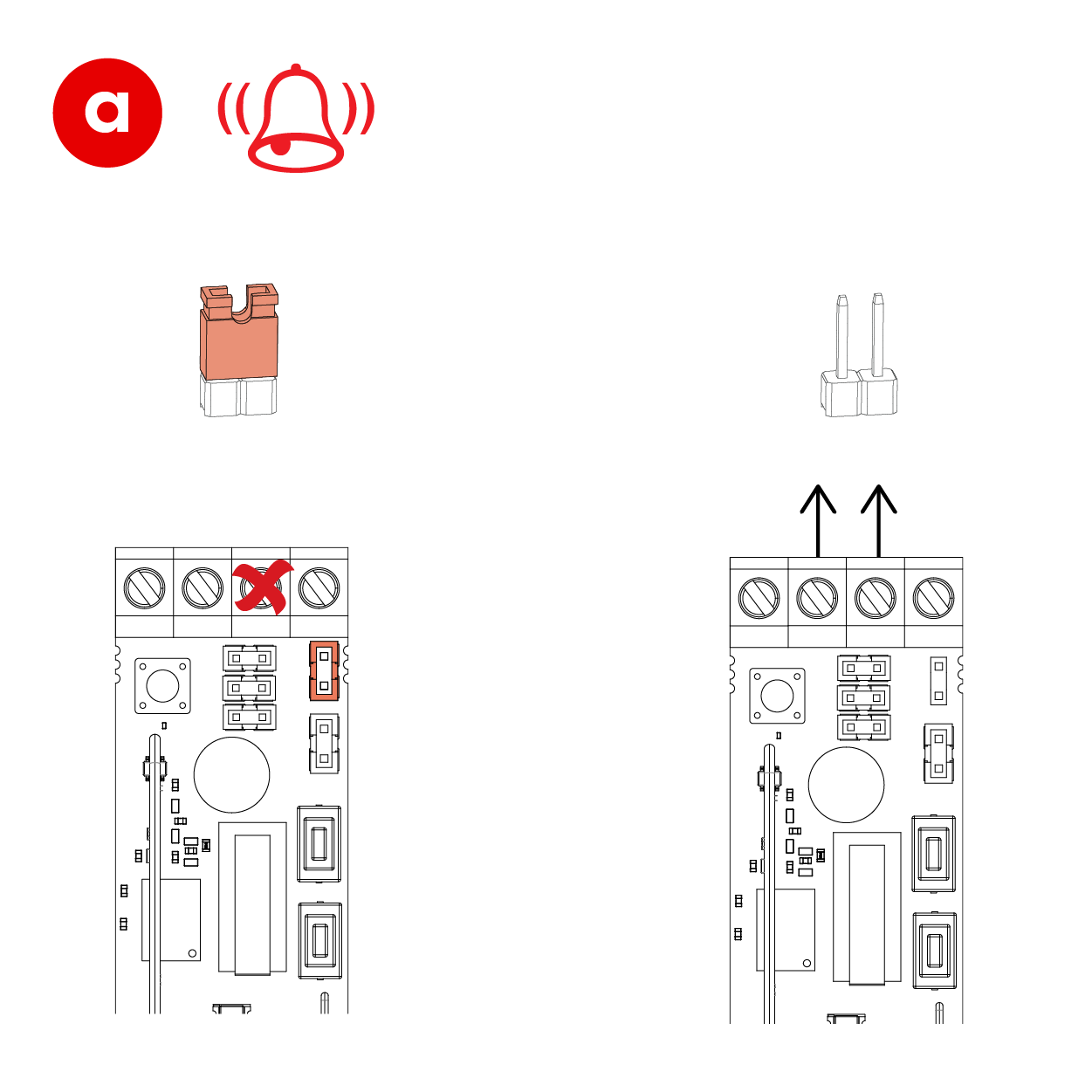
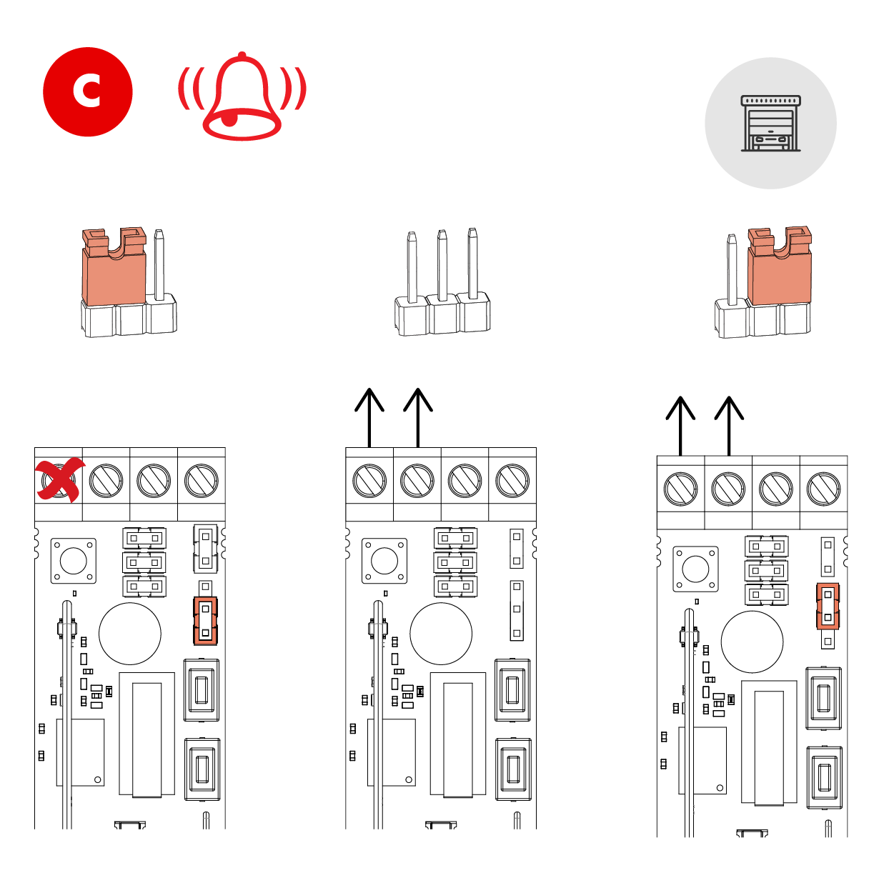
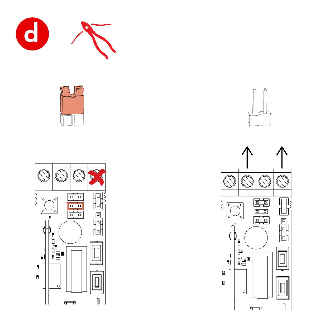
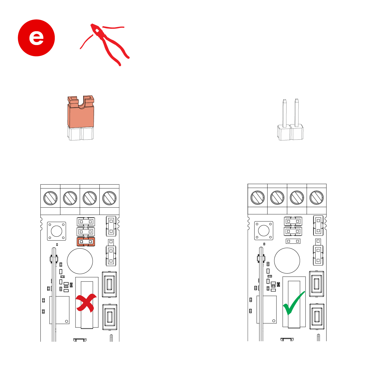
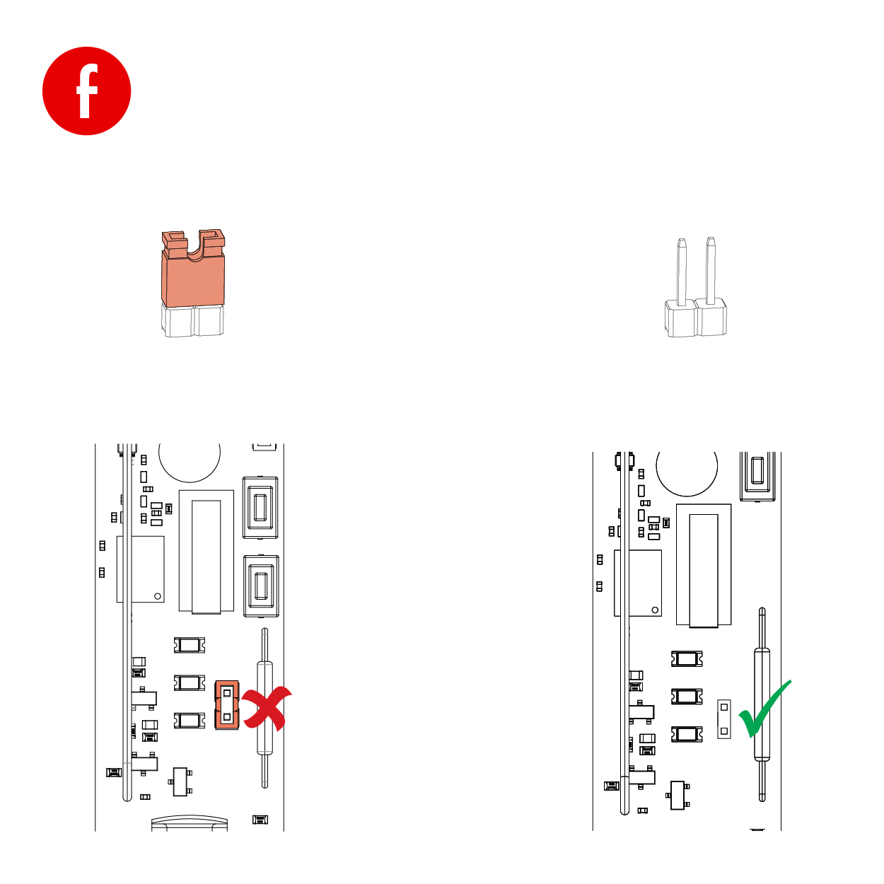
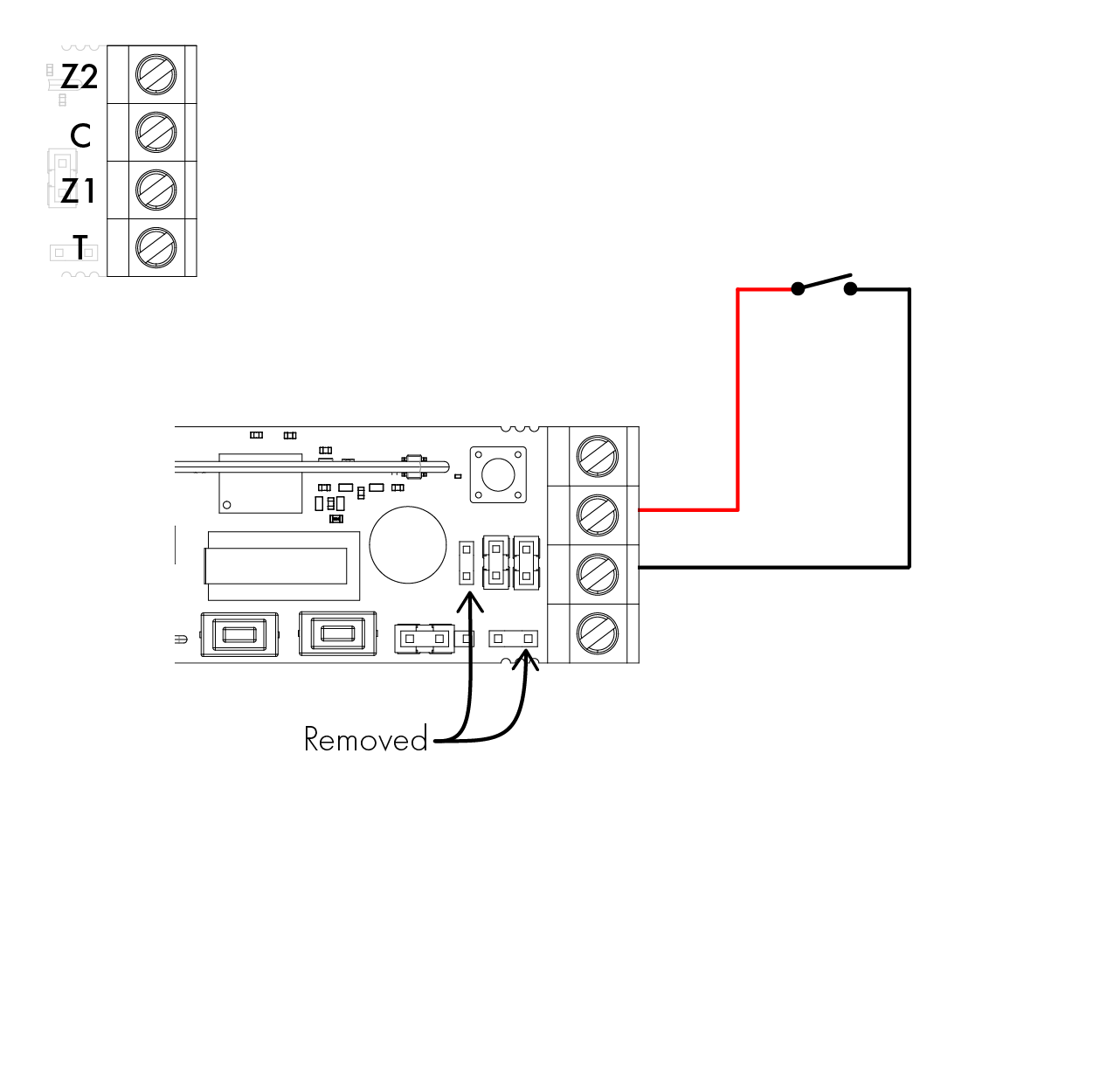
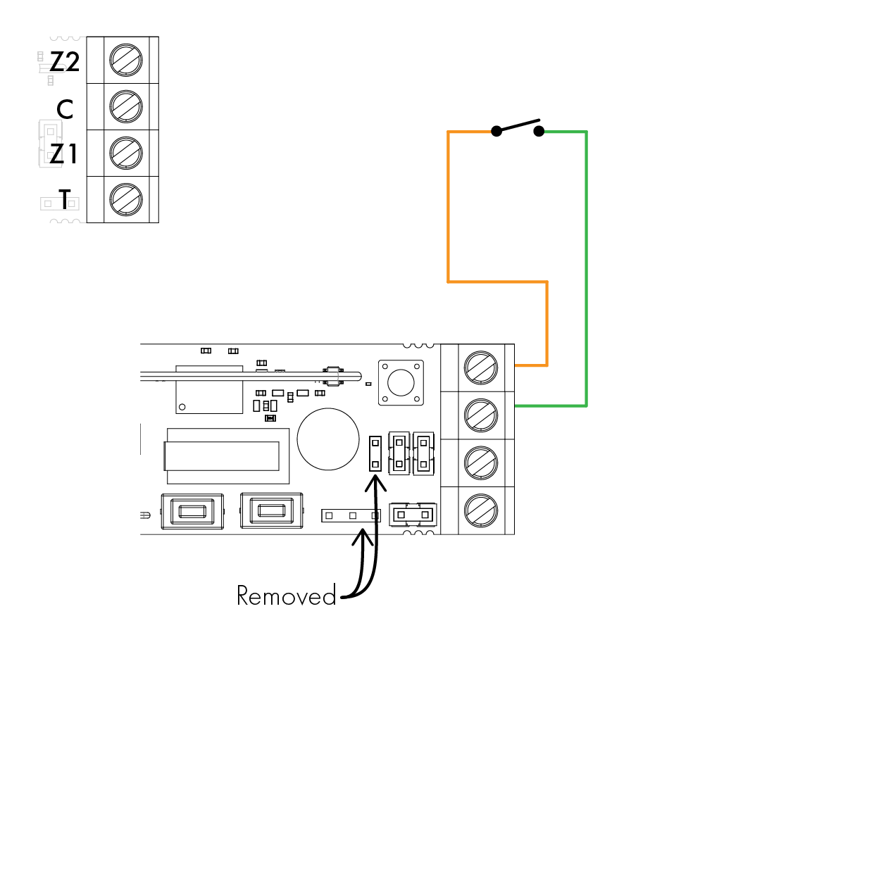
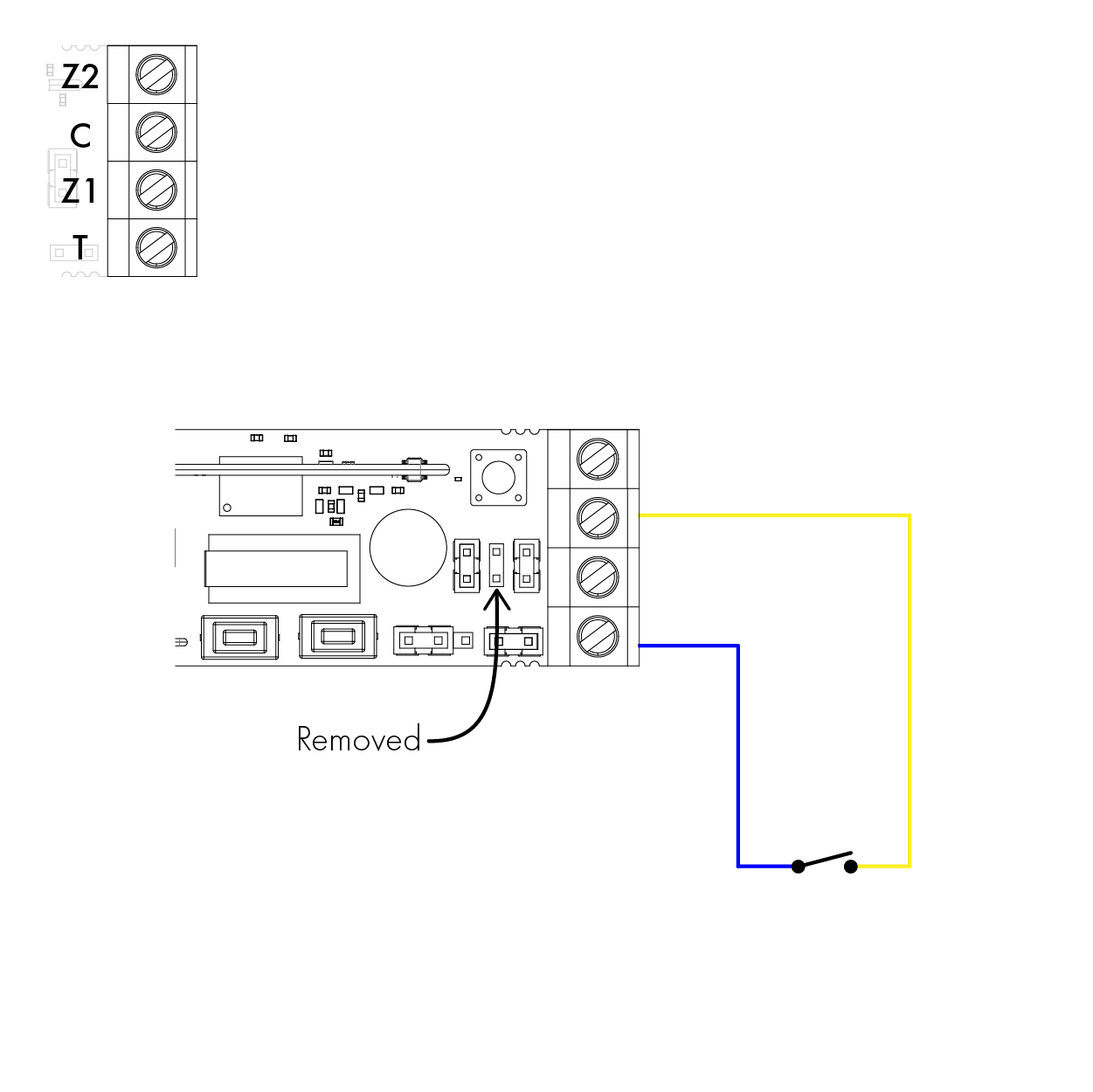
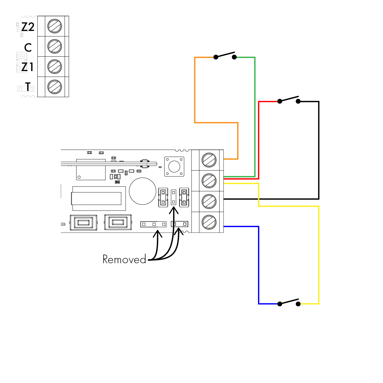
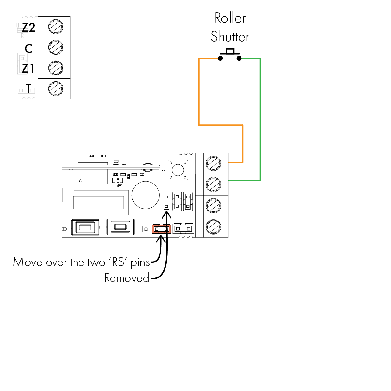
For any of the configurations utilising the external alarm circuit input, the reed switch of the device should be linked out. See section “C. Jumper headers”.
Please note: The colours for the circuits below are indicative and not the colours required to make the circuit work.
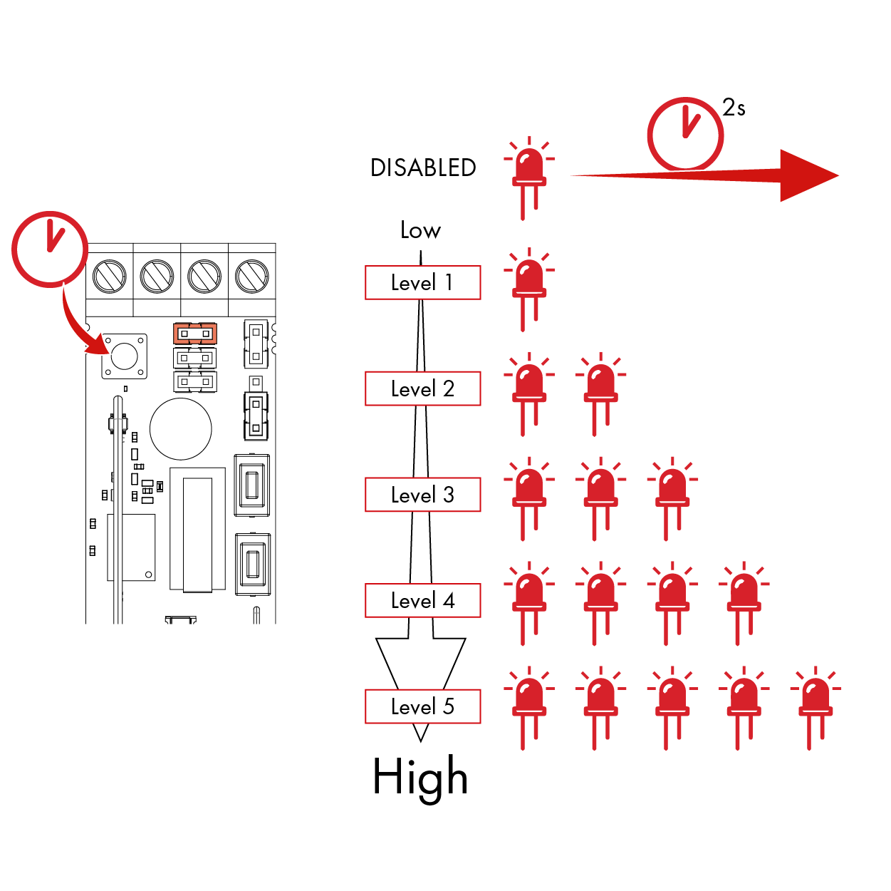
For the first 5 minutes after the device is powered up, the device enters calibration mode. This allows the installer to check that the zones are triggering as intended.
During this period, the blue alarm LED is disabled whilst the green and red LEDs indicate whether zone 1 or zone 2 are being triggered:
After this period of 5 minutes, up until an hour has passed, the blue alarm LED will light up if any of the shock sensor, reed switch or external inputs are triggered.
After 1 hour from power up, all LEDs on the device will be disabled however, this sequence can be initiated again by tampering the device.
For electrical products sold within the European Community. At the end of the electrical products life, it should not be disposed of with household waste. Please recycle where facilities exist. Check with your Local Authority or retailer for recycling advice in your country.
To prevent possible damage to components, any static charge on your body needs to be eliminated before touching the inside of the unit. This can be accomplished by touching some grounded/earthed metallic conductor such as a radiator/pipework immediately before replacing the batteries.
This product is sold subject to our standard warranty conditions and is warranted against defects in workmanship for a period of two years (battery excluded). In the interest of continuing care and design, Pyronix Ltd reserves the right to amend specifications, without giving prior notice. Please see the control panel programming manuals for further information or visit: www.pyronix.com/uk/terms-conditions-sales/
 Arming Devices
 Communication Devices
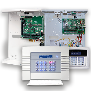 Control Panels
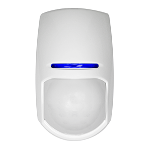 Detectors & Sensors
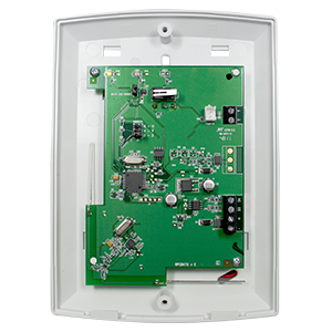 Expanders
 Legacy Products
 Smart Home Devices
 Software & Services
 Sounders & Bells
 Speech Diallers
 Wi-Fi Cameras