![]()
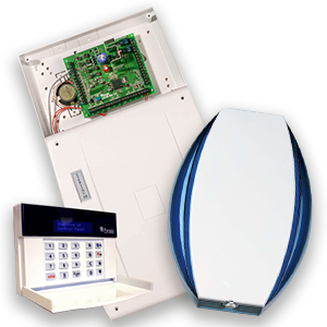
![]() Two-Way Wireless Security Protects Your Family and Property Without Compromise.
Two-Way Wireless Security Protects Your Family and Property Without Compromise.
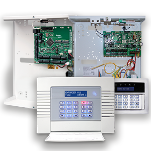
This wireless alarm system has been designed with your security in mind; with quick and easy installation and minimal maintenance, this system protects your home or property with a multitude of unique features.
Taking full advantage of the innovative two-way wireless technology, the wireless devices on this system are constantly communicating with each other, using High Security Wireless Encryption Protocol.
Compared to a conventional one-way wireless system where devices can be ‘asleep’ for up to five minutes at a time, therefore compromising your security, this wireless alarm system ensures your safety at your home or office at any
time.
This wireless alarm system has been engineered to be secure, reliable and easy to use. It includes the following features:
Battery Monitoring/Saving
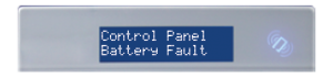
Advanced technology preserves the battery life of each wireless device. However, the system informs you when a battery needs replacing up to a month in advance before the device stops working. This key feature gives you enough time to change the battery in the specific device. Conventional wireless alarm systems may not give you a low battery warning signal, meaning that devices could stop working, leaving your environment unprotected.
User Friendly Keyfobs
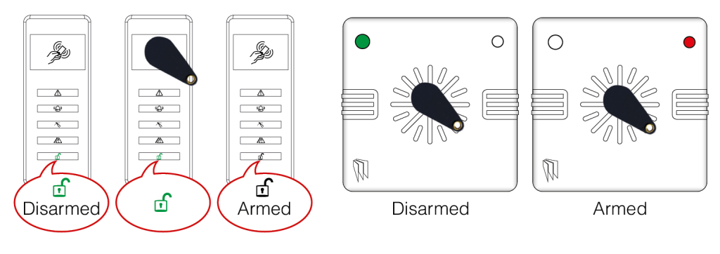
The fully two way wireless keyfob allows you to see the status of the control unit via three colour LEDs:
System arm: When the system is armed a red LED will illuminate
System disarm: When the system is disarmed a green LED will illuminate
System fault: When the system is in fault condition an amber LED will illuminate.
It is possible to allocate different functions to each keyfob such as arming/disarming different areas, activating outputs, requesting system status, and activating panic alarms. Up to 32 wireless keyfobs can be added to the
wireless alarm system. Each wireless keyfob has its own user ID which can be reported to the ARC and stored into the event log of the control panel individually. The keyfob also allows you to arm/disarm every area individually, giving you total control of your system.
User Automation Outputs
User automation outputs gives you the option to operate up to 20 devices such as gates, lights, sprinklers, etc. via your keypad or remotely via your keyfob, extending the use of your security system
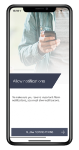
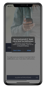
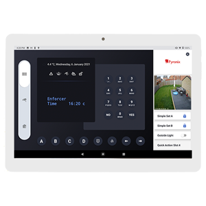
Push and Voice Notifications
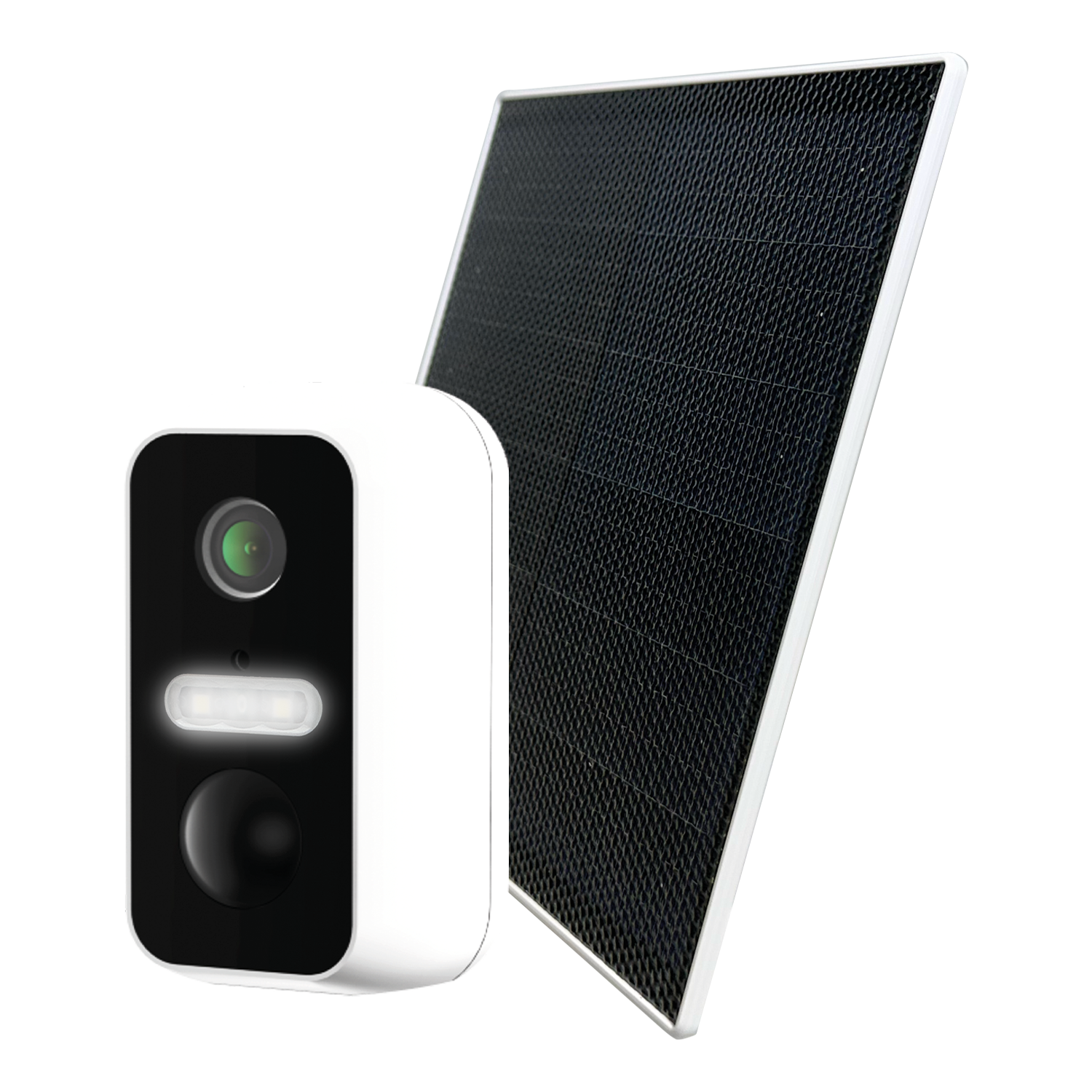
Receive instant push notifications from the control panel to HomeControl2.0 enabling you to react quicker to alarms. Combine the installation with Full HD Wi-Fi cameras for video verification as soon as the notification is received for peace of mind and higher security of your property.
HomeControl2.0 also delivers voice notifications alongside the push notifications simultaneously to make sure you never miss an incident, whether this be your alarm disarming, perimeter breached or panic alarm you will be the first to know.
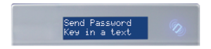
SMS Text Notifications
Receive notifications via SMS text messages of any incidents within your home in real time. This can be programmed to send a notification in different situations: System is armed or disarmed: Notification that your child has returned home from school safely. Alarm activation: Notification that the alarm has been triggered, allowing you to monitor your home from anywhere in the world.
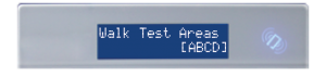
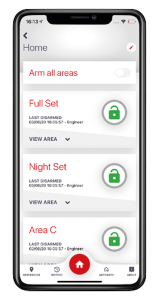
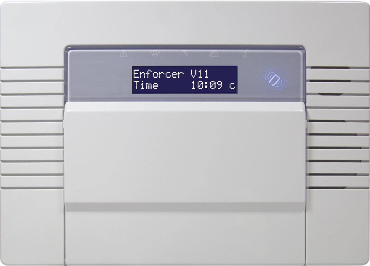
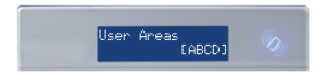
This wireless alarm system has 4 areas in which may be set up in the following way:
Area A: Full arm of the house
Area B: Downstairs disarmed. Upstairs armed.
Area C: Garage armed. Rest of house disarmed.
Your engineer will be able to design the system according to your needs.
Additional wired keypads may also be connected to the wireless control panel, please ask your engineer for more information.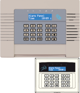

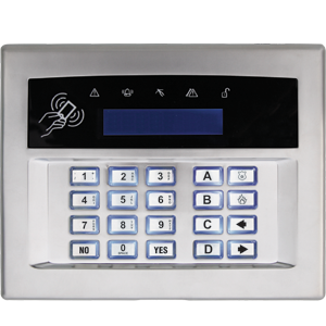
![]() = Exits the Master Manager menu and selects Area A when arming.
= Exits the Master Manager menu and selects Area A when arming.

![]() = Moves backwards in the Master Manager menu and selects Area B when arming.
= Moves backwards in the Master Manager menu and selects Area B when arming.

![]() = Enables chime, displays additional information in the event log, and selects Area C when arming.
= Enables chime, displays additional information in the event log, and selects Area C when arming.
 = Moves forward in the log, scrolls between options, enters the Master Manager menu and selects Area D when arming.

 = Not used unless specifically enabled by engineer.
![]()
![]() = Directional buttons and enables/disables functions.
= Directional buttons and enables/disables functions.
 = Enters menus and accepts programming preferences.
 = Cancels items, resets the panel and moves to next item in a menu item.
Tag readers can be used for arming/disarming, entry control or access control. Ask your engineer for more details.

![]()
| Proximity area (please present your tag here) | |
 |
Alert LED |
 |
Alarm LED |
 |
Tamper LED |
 |
Fault LED |
 |
Disarmed LED |
 To arm/disarm the system using the external tag reader, present a preprogrammed tag to the centre of the reader.The reader will display the system status:
Green LED means the system is disarmed.
Red LED means the system is armed.
Present the tag again within 10 seconds and the system will arm or disarm.
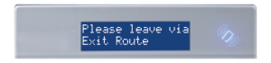
The system will then arm depending on the type of exit mode programmed
(final door, timed or push to set).
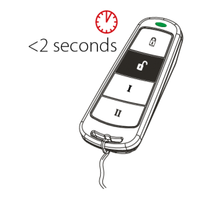
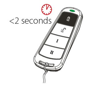
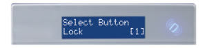
The wireless keyfob has four buttons that may be programmed for specific purposes, these options are programmed in the ‘EDIT USERS?’ section.
All four buttons on the keyfob may be locked so that any accidental presses will not affect your wireless alarm system. For example, this protects the buttons from being pressed accidentally if a keyfob is in someone’s pocket.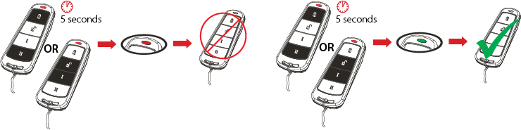 The buttons can be customised to operate as desired. The table below gives the defaults of how each button is programmed.
| LOCK | When pressed, the Area A will start to arm. | |
| UNLOCK | When pressed, the wireless alarm system will disarm any area that is already armed. | |
| I BUTTON |  |
When pressed, the Area B will start to arm. |
| II BUTTON |  |
When pressed, if the GREEN LED is shown then the wireless alarm system will be disarmed. If the RED LED is shown then the wireless alarm system will be armed. |
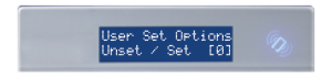
If one of the buttons is programmed as ‘Set Area’, the wireless alarm system can be armed by pressing the programmed button on the keyfob. The keypad will then start to count down the exit time, wait for a ‘final door’ to be opened and closed or wait for a Push to Set (PTS) button to be pressed (depending what exit mode is programmed as by the engineer).
Once the alarm panel is in this ‘arming’ stage, it is possible to ‘quick arm’ the system by pressing the same button again; this will reduce the time to arm to ‘immediate arming’. The alarm panel will revert to the normal display with the time showing, but a beep will be heard confirming the system has armed.
If you are using a proximity tag to arm or disarm the wireless alarm system, press 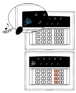 any key first (except ), to ‘wake’ the wireless arming system before presenting a tag.
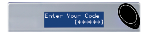
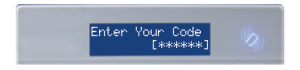
Alternatively, if a user code is being used, then enter the code. The wireless arming station will automatically ‘wake’ once the first button is pressed.
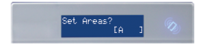
After a tag or code has been activated, choose the area to arm by pressing the , , or . The key will illuminate indicating that area has been chosen to be armed. Once confirmed, press the  key.
key.
To disarm, simply enter the user code.
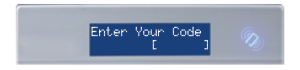
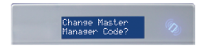
Press the key and enter the Master Manager code.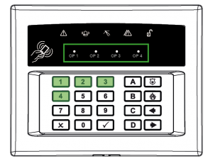
The keys 

 and
and  will illuminate.
The OP1–4 LEDs will illuminate once the 1-4 numeric keys have been pressed. Once illuminated, it signifies that the output has triggered. Press the key again to deactivate the output.
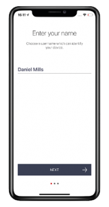
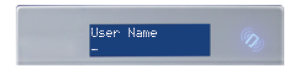
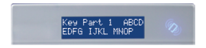
The wireless alarm system incorporates predictive text, so the system will predict which word is being spelt.
For example, if you want to type ‘Daniel’, press once and the name ‘David’ will appear. Using the ![]() and
and ![]() keys move the cursor under the ‘v’ and press
keys move the cursor under the ‘v’ and press  twice to change it to a ‘n’. The text will now change to ‘Daniel.’
Press to accept.
If the word that you require does not appear in the list, just continue typing the word letter by letter.In addition, the keys are used as follows:
= make the character into a capital
= move cursor left
= delete the character above the cursor
= moves cursor right
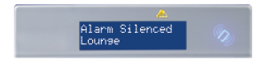
To disarm via a keyfob. Press  .
.
The keyfob LED will flash green indicating that the system has disarmed.
To disarm via a keyfob. Press .
The keyfob LED will start to flash green indicating that the system has disarmed.
Rearming the system after an alarm can only be done at the keypad.
If you have a tag reader installed, then it will be possible to arm and disarm the wireless alarm system using a tag (the same tags can also be used on the readers on the main control panel and keypads).
There are two types of readers that can be used with the wireless alarm system – the internal tag reader and the external tag reader (used both indoors and outdoors).
Tags for the readers need to be programmed through the ‘Edit Users’ function in the Master Manager Menu. The internal and external readers can be both assigned to individual areas, this will need to be set up by your engineer.
The readers may be used for entry control, which means they can operate automatic locks for example as well as arming and disarming the system. This can be set up by your engineer.
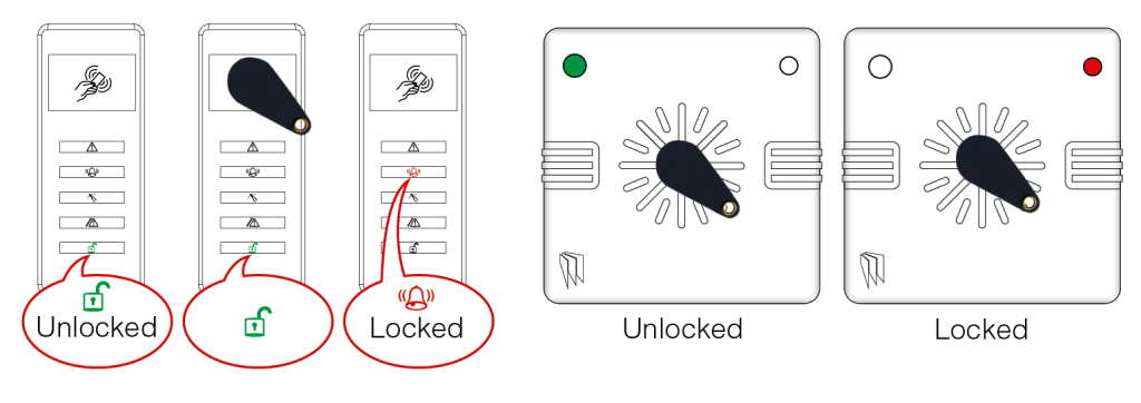
Arming
Present a valid tag to the reader, the green LED will illuminate on the external reader, remove the tag, the door will unlock, then present the same tag within 10 seconds and the system will arm and the door will lock.
Disarming
Present a valid tag to the reader and then remove it, the status will be shown (the alarm symbol will illuminate indicating the system is armed on the internal reader and the red LED on the external reader), present the same tag within 10 seconds again and the system will be disarmed, and the door will unlock.
Access Control/Entry Control
The readers can be used also for opening doors only without the ability to arm and disarm. Please contact your installer for more information on this feature.
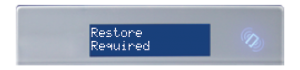
Your engineer may have set up the system so that either an ‘Anti-Code’ or ‘Engineer Restore’ is required in order to fully reset the wireless alarm system
If the panel is unable to arm for any reason, the keyfob status LED flashes amber indicating a fault is on the system.
The Master Manager menu has the following functions:
Set Date and Time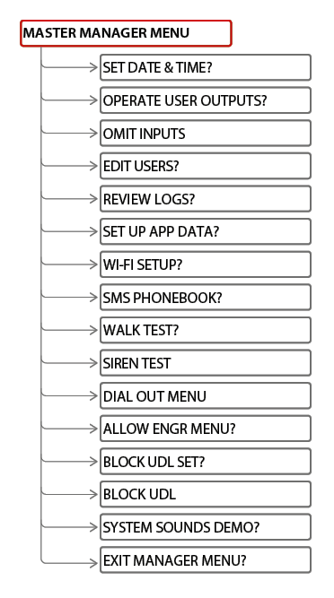
Programs the date and time.
Operate User Outputs
Activates/deactivates user automation outputs that are used to remotely activate devices, such as electronic gates & lights.
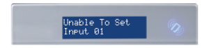
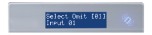
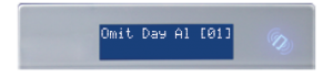
Omit Inputs
Bypasses zones programmed as ‘Day Alarm’ only.
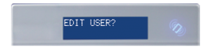
Edit Users
Adds/Edits/Deletes User PIN codes, tags and keyfobs.
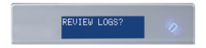
Review Logs
Displays all event log information.
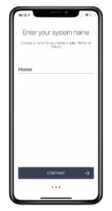
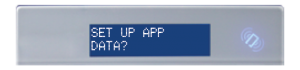
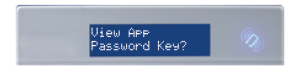
Set Up App Data
If the HomeControl2.0 App has been enabled, this function will control the settings.
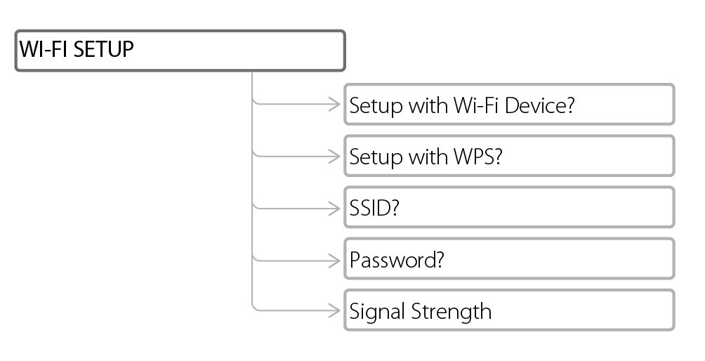
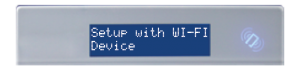
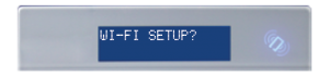
Wi-Fi Setup
Adds or changes a Wi-Fi connection with your router.
SMS Phonebook
If SMS texting is enabled, there can be up to 10 mobile numbers programmed to send SMS alarms. Please discuss this feature with your engineer if required.
Voice Phonebook
Edits the telephone numbers that the panel is programmed to send voice messages to.
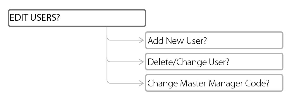
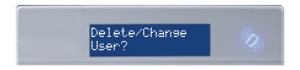
The ‘EDIT USERS’ function allows adding, editing and deleting of both master manager and user codes, tags and keyfobs.
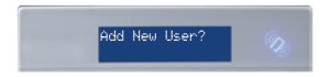
The control panel can have up to 80 users programmed. Each of the users are allocated a code, tag or a wireless keyfob.
Each wireless keyfob has four buttons that can be programmed for any of the following functions.
No Action
Disables the button.
Show Status
Prompts the LED on the keyfob to indicate whether the system is armed or disarm.
Set Area
Arms the chosen area(s)
Unset Area
Disarms the chosen area(s)
Operate Output
Triggers an output on the panel (programmed by Engineer)
Flexi-set allows you to choose which level/area to arm if a user code or tag is assigned to one or more levels/areas. If this function is disabled, when a user code is entered or proximity tag presented, the system will automatically arm the levels/areas that the user is assigned to.
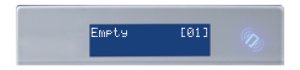
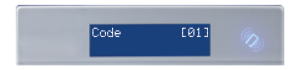
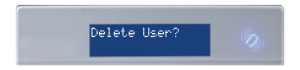
Deleting a User
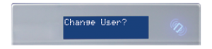
Changing a User

The ‘Review Logs’ function monitors all operational information of the wireless alarm system, such as arming/disarming information and alarm activations etc.
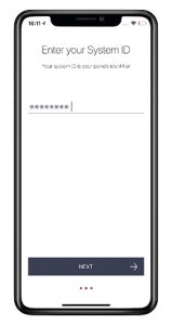
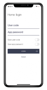
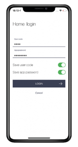
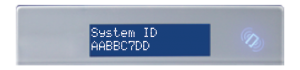
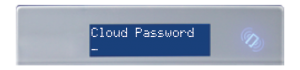
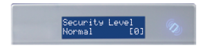
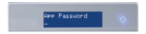
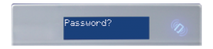
This menu is required in order to use the smart device application to control the system. When setting this menu up it is important to take note of the ‘System ID’, ‘App Password’ and ‘Cloud Password’.
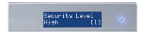
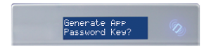
At this point you choose ‘normal’ security level or ’high’ security level. This does not compromise the security between the control panel and HomeControl2.0 but if high is selected, the panel will automatically generate a 32 digit app password for you.
Low Security
High Security
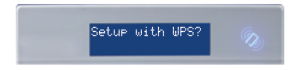
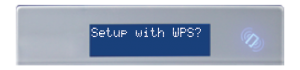
As this method is a little more complicated, please watch the video on this method by going to the following link https://bit.ly/wifi-setup
5. At this point, the router that the system is to connect to should be put in to WPS mode.
6. The panel will display a message to indicate when the system has successfully connected.

If SMS or voice messages are activated, there can be up to 10 mobile numbers programmed which can be changed in this function. If ‘do not use’ is shown on the display of a number, then a telephone number already exists that is communicating to an Alarm Receiving Centre (this can only be changed by your engineer).
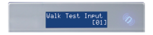
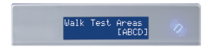
The ‘Walk Test’ function allows the testing of all programmed zones on the wireless alarm system.
This function is used to test any wired or wireless output on the panel programmed as ‘[0014] Siren Any’ and ‘[0016] Strobe Any’.
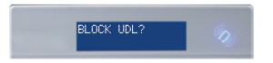
This function is used to force the panel to dial out to UDL software.
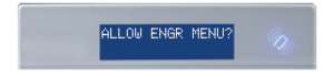
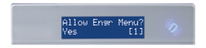
If this function is enabled, the engineer will require authorisation from you before they can access the engineering menu.
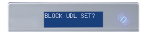
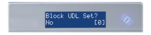
Your wireless alarm system may be configured so that your alarm installation company can remotely arm/disarm. Should you wish to block this access, you can enable this function.
If enabled, this option will block any upload/download software from connecting to the control panel.
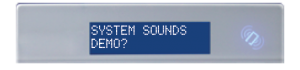
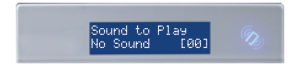
This function showcases all of the sounds that may occur from the panel during operation.
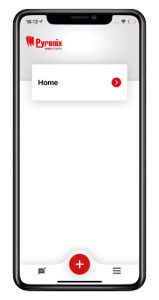
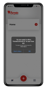
The app can be downloaded from either the Apple App Store or on Android from the Google Play Store by searching ‘HomeControl’.
Smart Device Minimum Requirements
iOS 7.0 or later
Android 4.0 or later
(This can be found in the Master Manager menu in ‘SET UP APP DATA?’)
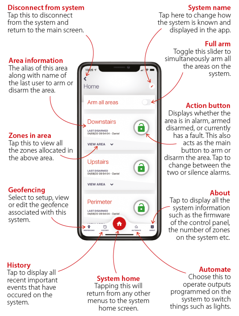
Action Button Icons
Individual Zone Icons
When you receive a phone call from your control panel, pick up the phone (or press the answer button /option on your mobile phone) and the control panel will listen until it hears an audible response on the line: simply answer ‘hello’ or make any other audible sound.
Once the panel detects the sound you have made – it will begin playing a sound recording that corresponds to the events that have been triggered. A typical message will tend to include details of which user armed or disarmed your system, what event occurred or which sensor triggered. The system contains countless voice recordings that are assembled into the correct message for the specific situation at hand.
If your alarm system has been configured by your engineer to request an acknowledgement code – then once the details of the alert message have been played it will be requested at the end of the phone call from the panel. This is a numerical code that you must enter on your phone followed by the # (hash) key.
All wireless devices comply with the following EU requirements
| EMC | 2014/30/EU |
| Low Voltage | 2014/35/EU |
| RE Directive | 2014/53/EU |
| RoHS | 2011/65/EU |
And meet the following standards where relevant:
| EN 61000-6-3:2007 +A1:2011 | EMC. Generic emission standard. Residential, commercial and light industry |
| EN 50130-4:2011 +A1:2014 | Immunity requirements for components of fire, intruder and social Wireless Alarm Systems |
| EN 62368-1:2014+A11:2017 | Audio/video, information and communication technology equipment. Safety requirements |
| EN 50131-5-3:2005+ A1:2008 | Grade 2. Interconnections for equipment using radio frequency techniques |
| ETSI EN 301489-3:2000 | EMC. Radio equipment. Part 3: Short range devices (SRD) 9kHz to 40GHz |
| ETSI EN 300 220 | EMC. Receiver Class 1, Environmental Category 1 |
| CERT/ERC | Recommendation 70-03 Annex 1 |
Compliant operation is only guaranteed when installed and operated according to the relevant installation and user manuals.
Your panel is suitable for use in installations designed to meet the European requirements of Security Grade 2, Environmental Class II. When all parts are working normally, this equipment in combination with the PSTN or GSM and suitable ARC equipment will meet the requirements of ATS2 /LAN or WiFI or GPRS meet the requirements of ATS5
External arm/disarm readers and wireless sirens meet the requirements of environmental class 4.
Number of Code Differs: Tag hex code.
Your panel is designed to automatically inhibit certain functionality.
Keypad
After 30 key presses without entering a valid code, keys are disabled for 90 seconds. After reinstatement, this will be repeated after each 7 key presses until a valid code is entered.
Proximity Tag Reader (Or Reader at a Keypad)
After 6 presentations of an invalid tag, the reader will be disabled for 90 seconds. After reinstatement, this will be repeated for each invalid tag until a valid tag is used.
 Arming Devices
 Communication Devices
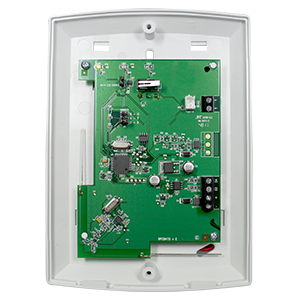
 Control Panels
 Detectors & Sensors
 Expanders
 Legacy Products
 Smart Home Devices
 Software & Services
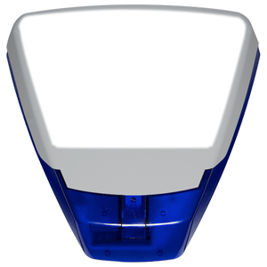 Sounders & Bells
 Wi-Fi Cameras


 to scroll to ‘REVIEW LOGS?’. Press
  .
.
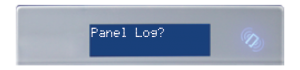
 or
or  to scroll backwards and forwards through the log.
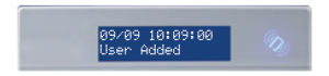
 key to show more information (such as which zone activated, or which user armed the system etc.)
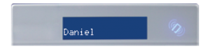


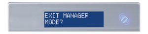
 to exit and save.