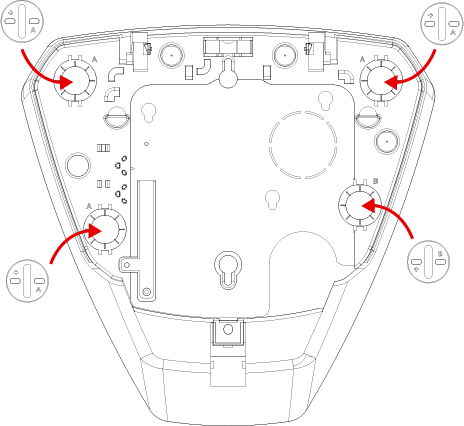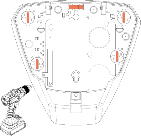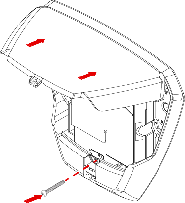
Please note: It is important that the base is securely affixed to the wall therefore the surface texture and material should be taken into account when choosing the plugs, screws etc.
For a standard brick wall, we recommend using a 7mm masonry drill bit, brown wall plugs and 10 x 2” screws.
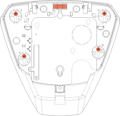
When you are ready to learn the device to the control panel or wireless expansion module, enter pairing mode on the system (for more details, please see system guide).
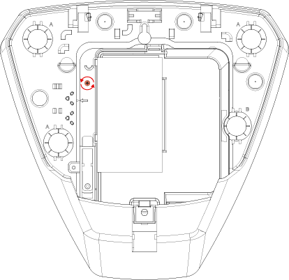
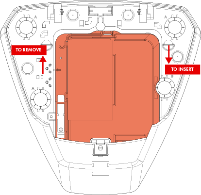
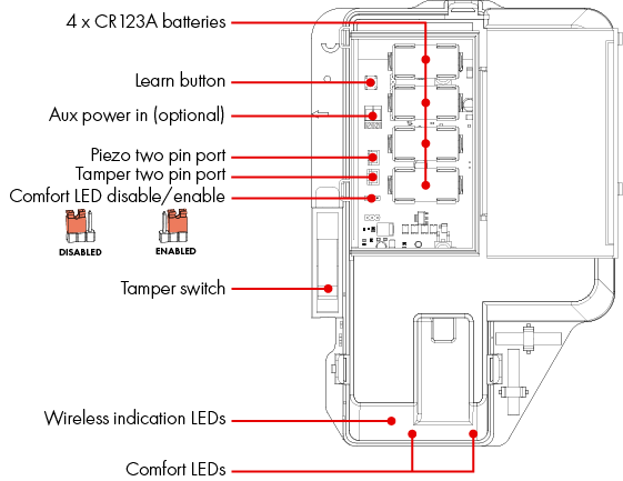
Once the system is in pairing mode, remove the pieces of plastic insulation to enable the batteries and power up the device.
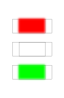
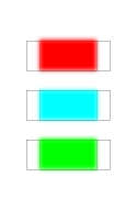
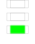
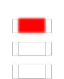
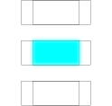
The LEDs on the device will indicate the status and/or result of the pairing process.
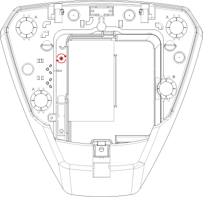
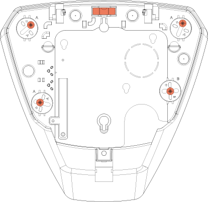
Important: When replacing the batteries in the device, all four batteries must be replaced at the same time.
For electrical products sold within the European Community. At the end of the electrical products life, it should not be disposed of with household waste. Please recycle where facilities exist. Check with your Local Authority or retailer for recycling advice in your country.
To prevent possible damage to components, any static charge on your body needs to be eliminated before touching the inside of the unit. This can be accomplished by touching some grounded/earthed metallic conductor such as a radiator/pipework immediately before replacing the batteries.
This product is sold subject to our standard warranty conditions and is warranted against defects in workmanship for a period of two years (battery excluded). In the interest of continuing care and design, Pyronix Ltd reserves the right to amend specifications, without giving prior notice. Please see the control panel programming manuals for further information or visit: www.pyronix.com/uk/terms-conditions-sales/
 Arming Devices
 Communication Devices
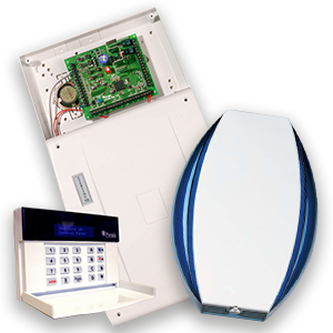
 Control Panels
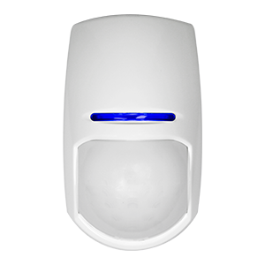 Detectors & Sensors
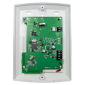 Expanders
 Legacy Products
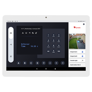 Smart Home Devices
 Software & Services
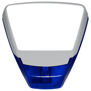 Sounders & Bells
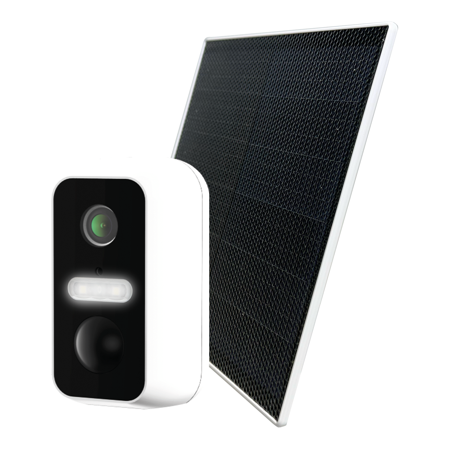 Wi-Fi Cameras